|
omdl
v0.6.1
OpenSCAD Mechanical Design Library
|
|
omdl
v0.6.1
OpenSCAD Mechanical Design Library
|
Shape extrusion tools. More...
 Collaboration diagram for Extrude:
Files | |
| file | tools_utility.scad |
| Shape transformation utility tools. | |
Functions | |
| module | rotate_extrude_tr (r, pa=0, ra=360, profile=false) |
| Translate, rotate, and revolve the 2d shape about the z-axis. More... | |
| module | rotate_extrude_tre (r, l, pa=0, ra=360, m=255, profile=false) |
| Translate, rotate, and revolve the 2d shape about the z-axis with linear elongation. More... | |
| module | linear_extrude_uls (h, center=false) |
| Linearly extrude 2d shape with extrusion upper and lower scaling. More... | |
Shape extrusion tools.
| module linear_extrude_uls | ( | h | , |
| center | = false |
||
| ) |
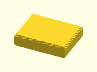
Linearly extrude 2d shape with extrusion upper and lower scaling.
| h | <decimal-list-3:9|decimal> A list of decimals or a single decimal to specify simple extrusion height. |
| center | <boolean> Center extrusion about origin. |
When h is a decimal, the shape is extruded linearly as normal. To scale the upper and lower slices of the extrusion, h must be assigned a list with a minimum of three decimal values as described in the following table.
| sym | h[n] | default | description |
|---|---|---|---|
| h | 0 | total extrusion height | |
| n1 | 1 | (+z) number of scaled extrusion slices | |
| h1 | 2 | (+z) extrusion scale percentage | |
| x1 | 3 | -h1 | (+z) x-dimension scale percentage |
| y1 | 4 | x1 | (+z) y-dimension scale percentage |
| n2 | 5 | n1 | (-z) number of scaled extrusion slices |
| h2 | 6 | h1 | (-z) extrusion scale percentage |
| x2 | 7 | x1 | (-z) x-dimension scale percentage |
| y2 | 8 | y1 | (-z) y-dimension scale percentage |
Example
Definition at line 234 of file tools_utility.scad.
Here is the call graph for this function: Here is the caller graph for this function:| module rotate_extrude_tr | ( | r | , |
| pa | = 0, |
||
| ra | = 360, |
||
| profile | = false |
||
| ) |
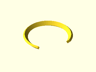
Translate, rotate, and revolve the 2d shape about the z-axis.
| r | <decimal> The rotation radius. |
| pa | <decimal> The profile pitch angle in degrees. |
| ra | <decimal> The rotation sweep angle in degrees. |
| profile | <boolean> Show profile only (do not extrude). |
Example
Definition at line 104 of file tools_utility.scad.
Here is the caller graph for this function:| module rotate_extrude_tre | ( | r | , |
| l | , | ||
| pa | = 0, |
||
| ra | = 360, |
||
| m | = 255, |
||
| profile | = false |
||
| ) |
Translate, rotate, and revolve the 2d shape about the z-axis with linear elongation.
| r | <decimal> The rotation radius. |
| l | <decimal-list-2|decimal> The elongation length. A list [x, y] of decimals or a single decimal for (x=y) |
| pa | <decimal> The profile pitch angle in degrees. |
| ra | <decimal> The rotation sweep angle in degrees. |
| m | <integer> The section render mode. An 8-bit encoded integer that indicates the revolution sections to render. Bit values 1 enables the corresponding section and bit values 0 are disabled. Sections are assigned to the bit position in counter-clockwise order. |
| profile | <boolean> Show profile only (do not extrude). |
Example
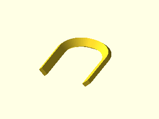
(l > 0), ra is ignored. However, m may be used to control which complete revolution section to render. Definition at line 140 of file tools_utility.scad.
Here is the call graph for this function: Here is the caller graph for this function:
