 |
omdl
v0.9.8
OpenSCAD Mechanical Design Library
|
 |
omdl
v0.9.8
OpenSCAD Mechanical Design Library
|
Screws, bolts and fastener bores. More...
 Collaboration diagram for Screws and Bolts:
Files | |
| file | screws.scad |
| Screws, bolts and fastener bores. | |
Functions | |
| module | screw_bore (d=1, l=1, h, n, t, s, f, a) |
| Flat and beveled-head fastener bore with nut, nut slot, and bore tolerance. More... | |
| module | screw_bore_tsf (d=1, l=1, t, a) |
| Gapped fastener bore with engagement cylinders for self-forming threads. More... | |
Screws, bolts and fastener bores.
| Requires: |
|---|
| include <omdl-base.scad>; |
| include <models/3d/fastener/screws.scad>; |
| module screw_bore | ( | d | = 1, |
| l | = 1, |
||
| h | , | ||
| n | , | ||
| t | , | ||
| s | , | ||
| f | , | ||
| a | |||
| ) |
Flat and beveled-head fastener bore with nut, nut slot, and bore tolerance.
| d | <decimal> bore diameter. |
| l | <decimal> bore length. |
| h | <decimal-list-5> fastener head; a list [hs, hf, hb, hg, hr], the head size, flat-height, bevel-height, side geometry (flat side count), and rotation. The head size is measured flat-to-flat when hg is specified. |
| n | <decimal-list-5> fastener nut; a list [ns, nf, nb, ng, nr, no], the nut size, flat-height, bevel-height, side geometry (flat side count), rotation, and bottom offset. The nut size is measured flat-to-flat. |
| t | <decimal-list-2> bore tolerance; a list [tx, ty], the tolerance along the x and/or y axis. |
| s | <decimal-list-list-3> nut slot cutout; a list of lists [sx, sy, sz], the list of slot sizes along the x, y, and/or z axis. Each of sx, sy, or sz can be a decimal list, such as [lower, upper], or a single decimal value, to cover [0, value]. |
| f | <decimal-list-2 | decimal> bore scale factor; a list [fd, fh], the bore diameter and bore height scale factors, or a single decimal to specify fd only. The default values for both are 1 (fh scales only the fastener head and nut heights). |
| a | <integer> z-alignment index; one of eight presets. |
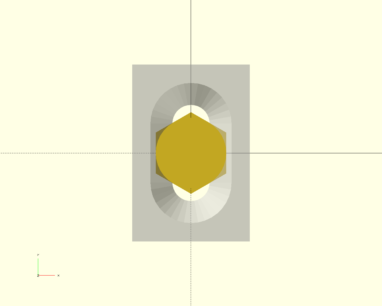
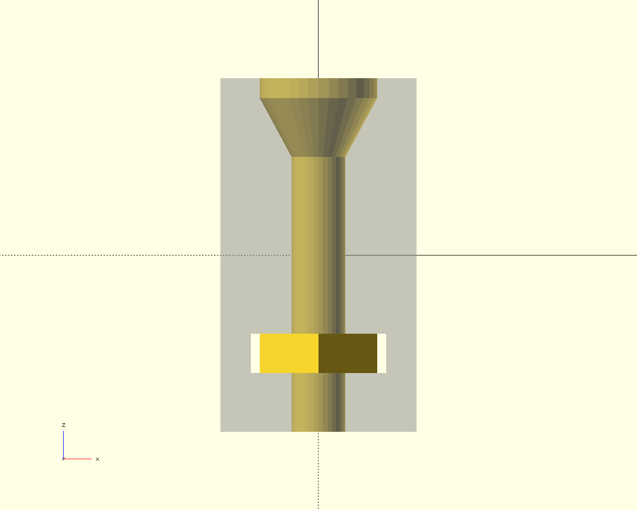
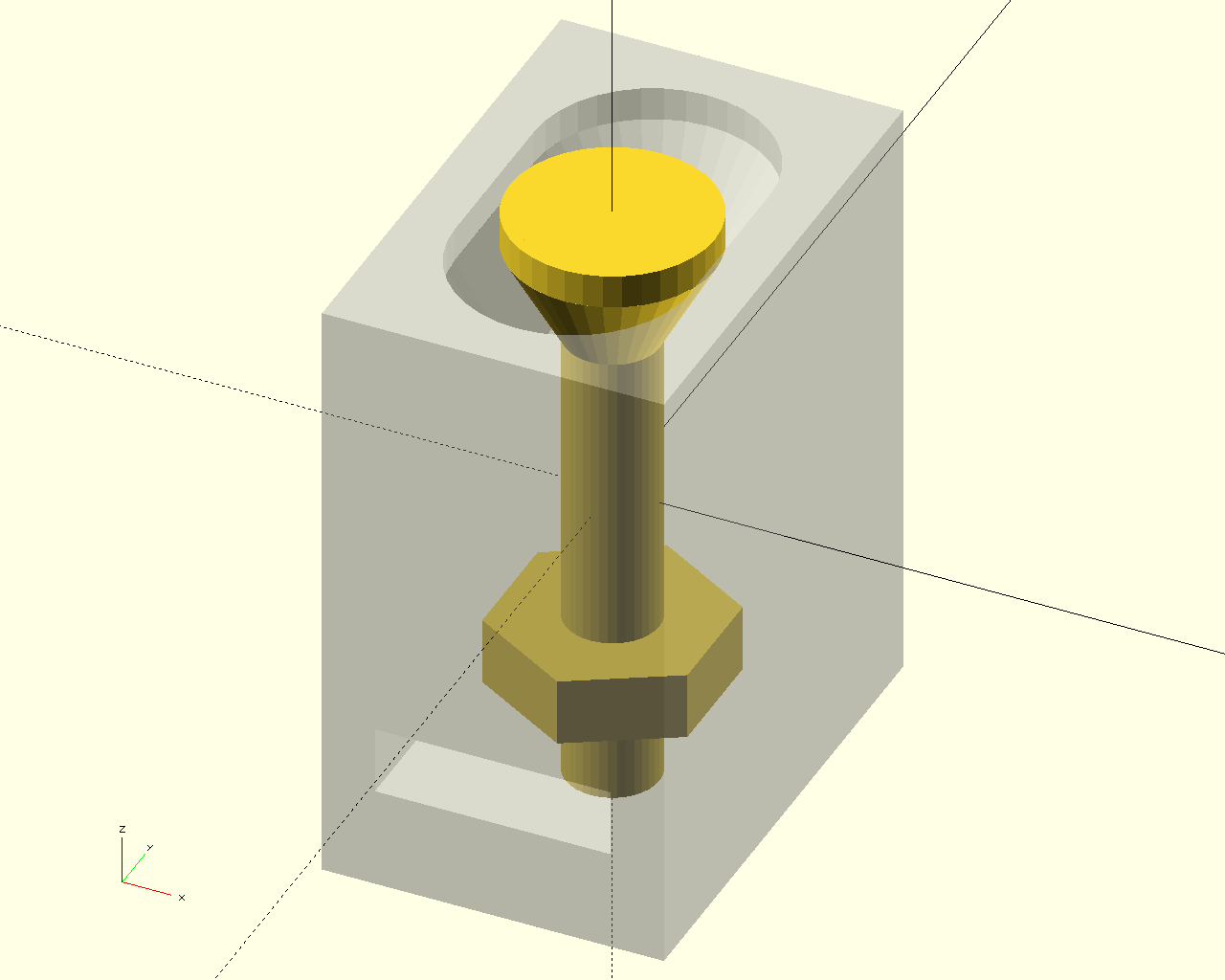
Construct a bore for a fastener hole, fastener head, and/or fastener nut. Both the head and nut are optional. A tolerance can be specified along the bore x and y axis. A nut slot cutout can be specified along the x, y, or z axis. The following example uses both tolerance and a nut slot along the y axis. For convenience, exact fastener dimensions can be specified along with the an appropriately selected scale factor f to slightly increase the bore for acceptable fastener fit.
Fastener bore examples script
| top | front | diag |
|---|---|---|
 |  |  |
Definition at line 357 of file screws.scad.
 Here is the call graph for this function:
 Here is the caller graph for this function:
| module screw_bore_tsf | ( | d | = 1, |
| l | = 1, |
||
| t | , | ||
| a | |||
| ) |
Gapped fastener bore with engagement cylinders for self-forming threads.
| d | <decimal> fastener diameter. |
| l | <decimal> bore length. |
| t | <datastruct> thread engagement (see below). |
| a | <integer> z-alignment index; one of five presets. |
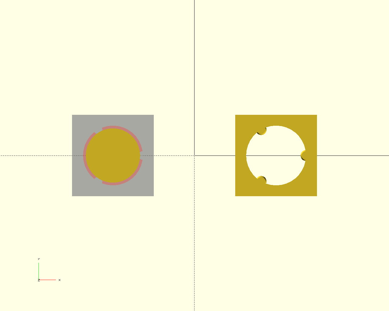
Construct a fastener bore with a gap for chip expansion and radial cylinders that engage with the inserted fastener threads to self-form counter-threads along the cylinder lengths. The bore is enlarged by a configurable gap which facilitates thread formation with reduced stress accumulation to the bore internal dimensions.
| e | data type | default value | parameter description |
|---|---|---|---|
| 0 | <decimal> | 5 | radial engagement percentage |
| 1 | <decimal> | 5 | radial gap percentage |
| 2 | <decimal> | 0 | rotational offset |
| 3 | <decimal> | 0 | radial offset |
| 4 | <integer> | 3 | cylinder count |
| 5 | <decimal-list-2 | decimal> | [8/10, 10] | cylinder upper taper: [f, h%] |
| 6 | <decimal-list-2 | decimal> | [ 0, 10] | cylinder lower taper: [f, h%] |
The diameter of the thread engagement cylinders can be configured to gradually change along the bore height from either the bottom, top, or both. The first element sets the cylinder diameter-scale factor and the second sets the length over which the scaling is performed. For f > 1, the cylinder diameter will increase in size, and for f < 1, the cylinder diameter will decrease in size.
Screw bore example script
| top | front | diag |
|---|---|---|
 | 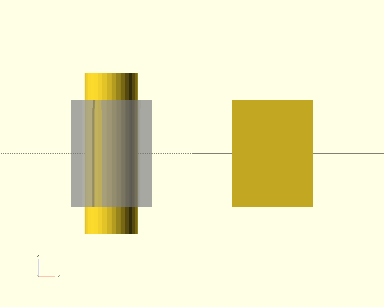 | 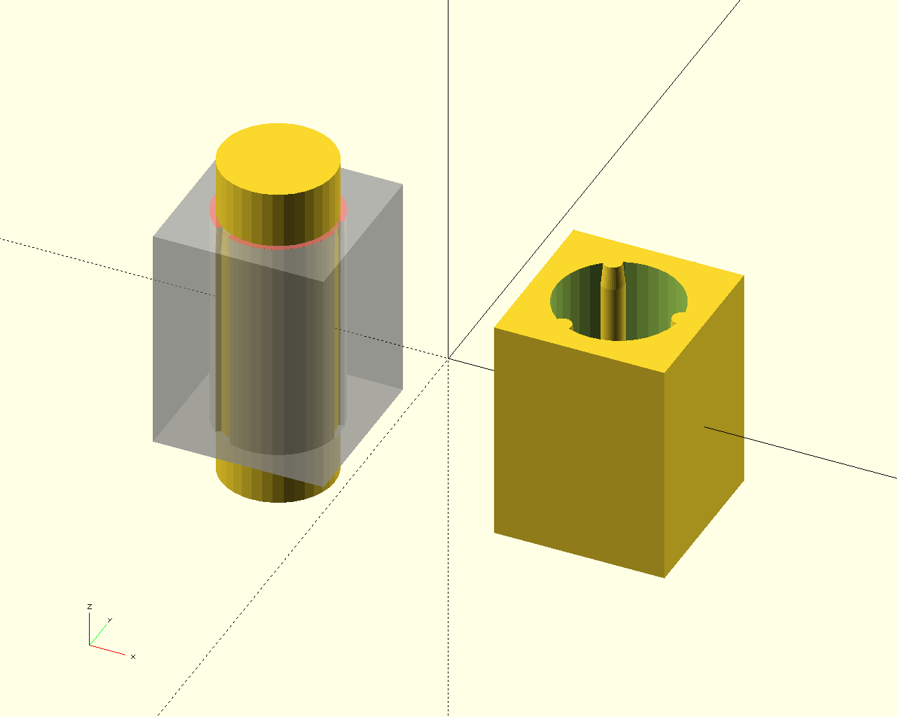 |
Definition at line 694 of file screws.scad.
 Here is the call graph for this function:
 Here is the caller graph for this function: