 |
omdl
v0.9.5
OpenSCAD Mechanical Design Library
|
 |
omdl
v0.9.5
OpenSCAD Mechanical Design Library
|
Rectangular prism project box generator. More...
 Collaboration diagram for Rectangular project box:
Files | |
| file | project_box_rectangle.scad |
| A rectangular box maker for project boxes, enclosures and housings. | |
Functions | |
| module | project_box_rectangle (wth, h, size, vr, vrm, inset, lid, lip, rib, wall, post, align, mode=0, verb=0) |
| A rectangular box maker for project boxes, enclosures and housings. More... | |
Rectangular prism project box generator.
| Requires: |
|---|
| include <omdl-base.scad>; |
| include <tools/operation_cs.scad>; |
| include <parts/3d/enclosure/project_box_rectangle.scad>; |
| module project_box_rectangle | ( | wth | , |
| h | , | ||
| size | , | ||
| vr | , | ||
| vrm | , | ||
| inset | , | ||
| lid | , | ||
| lip | , | ||
| rib | , | ||
| wall | , | ||
| post | , | ||
| align | , | ||
| mode | = 0, |
||
| verb | = 0 |
||
| ) |
A rectangular box maker for project boxes, enclosures and housings.
| wth | <decimal> wall thickness. |
| h | <datastruct | decimal> box extrusion height; structured data or a single decimal to set the box height. |
| size | <decimal-list-2 | decimal> box base size; a list [x, y] or a single decimal for (x=y). |
| vr | <decimal-list-4 | decimal> wall corner rounding radius; a list [v1r, v2r, v3r, v4r] or a single decimal for (v1r=v2r=v3r=v4r). |
| vrm | <integer-list-4 | integer> wall corner rounding mode = {0:none, 1:bevel, 2:round}; a list [v1rm, v2rm, v3rm, v4rm] or a single decimal for (v1rm=v2rm=v3rm=v4rm). |
| inset | <decimal-list-2 | decimal> wall-to-lid negative offset; a list [x, y] or a single decimal for (x=y). |
| lid | <datastruct | decimal> lid extrusion height; structured data or a single decimal to set the lid height. |
| lip | <datastruct | integer> wall lip; structured data or a single integer to set the lip mode. |
| rib | <datastruct | integer> wall ribs; structured data or a single integer to set the rib mode. |
| wall | <datastruct> interior walls; structured data. |
| post | <datastruct> posts; structured data. |
| align | <integer-list-3> box alignment; a list [x, y, z]. |
| mode | <integer> module mode of operation. |
| verb | <integer> console output verbosity {0=quiet, 1=info, 2=details}. |
Construct a rectangular enclosure for electronic and or other project boxes of the like. This module is designed to construct no more than one attached exterior cover and four exterior walls for each invocation. Therefore, a minimum of two invocations are required to construct a complete enclosure with six sides (top, walls, and bottom). Only the parameters wth and size are require; all others are optional.
In a simple case, a box would consist of a (1) cover with attached walls and (2) a separate opposite cover, without walls, to close the box. This would require exactly two invocations. More than two invocations can be used to construct boxes with multiple mid-sections and/or removable covers on one or both sides as shown in the following example.
Muilti-section project box example script
| front | diag |
|---|---|
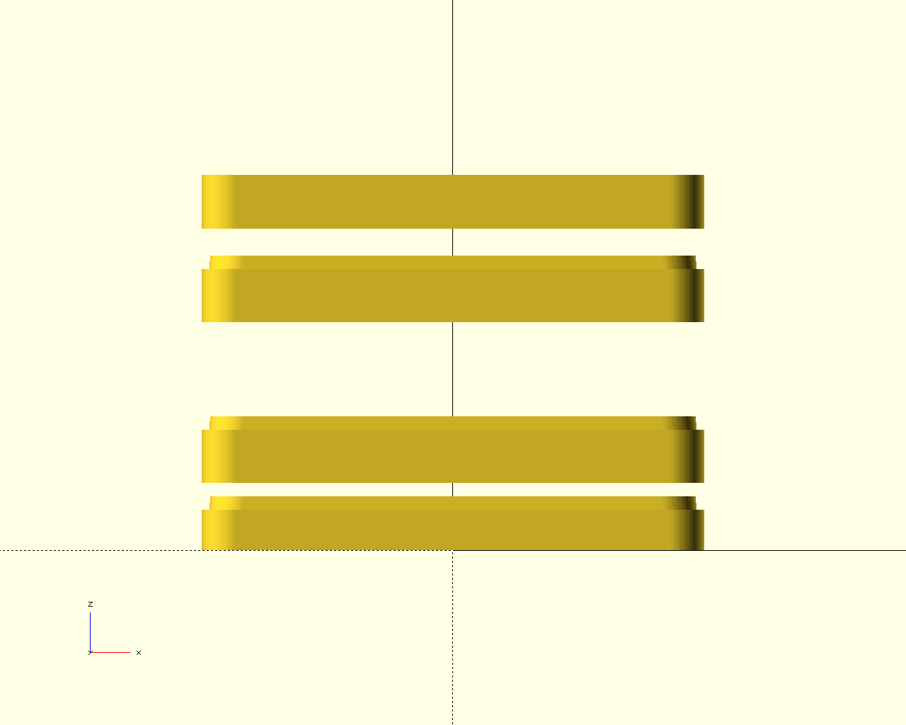 | 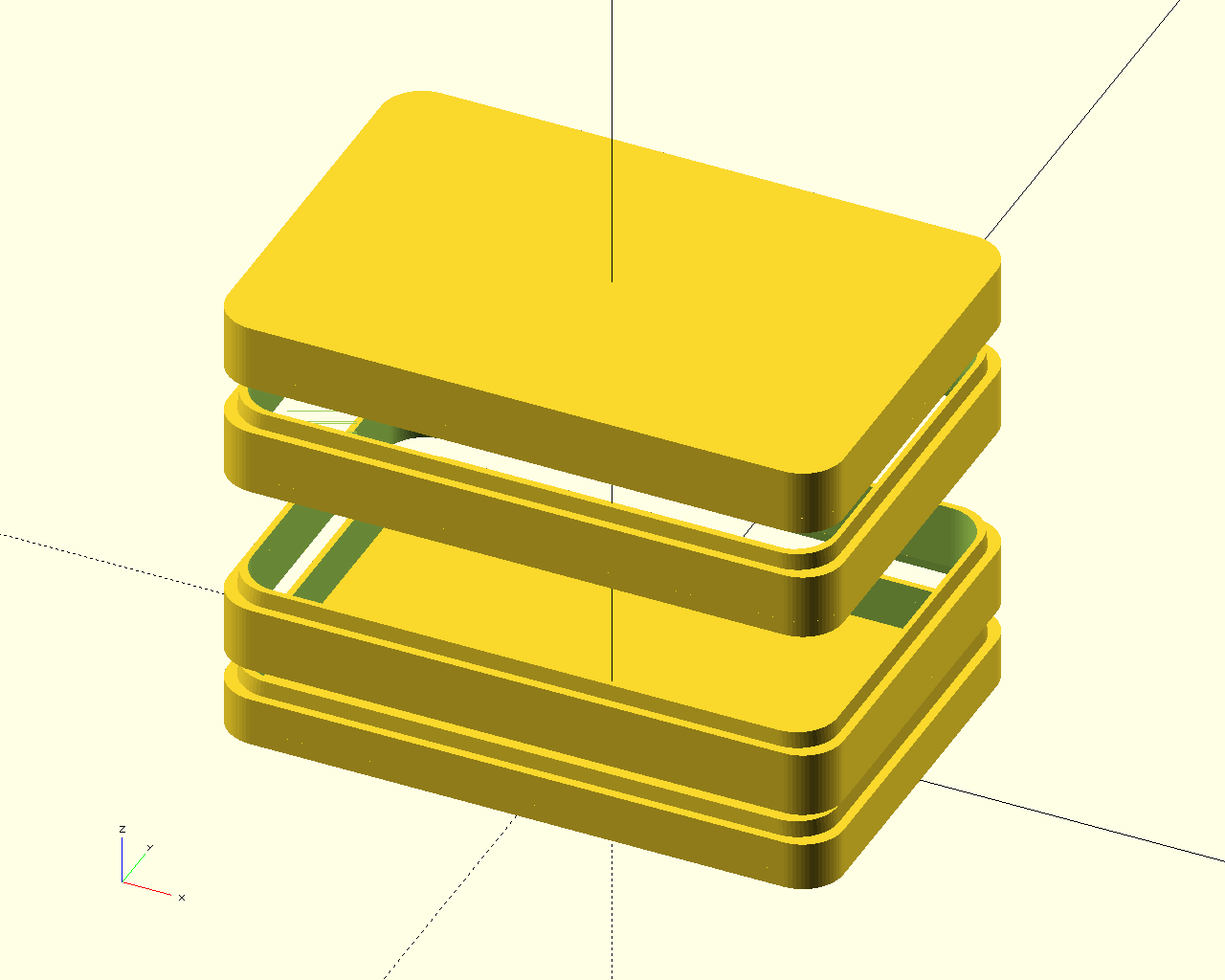 |
Notice that the middle sections omit the lid parameter to skip cover construction in this example.
Default values are calculated for all parameters. In some cases, the defaults are calculated based on prior user supplied values. For example, post diameters are calculated based on the supplied screw size for a post instance. Whenever a configuration consists of a list of values, there is no requirement to supply values for all elements of the list. Generally speaking, the list may be terminated at the parameter of interest. The caveat is for parameters of interest that comes after those which are not of interest. In this case, the prior values may be assigned a suitable value or may be assigned the value undef to use the calculated default as demonstrated below.
The edge rounding during shape construction is performed using the function polygon_round_eve_all_p(). Refer to its documentation for more information on the rounding modes and their descriptions.
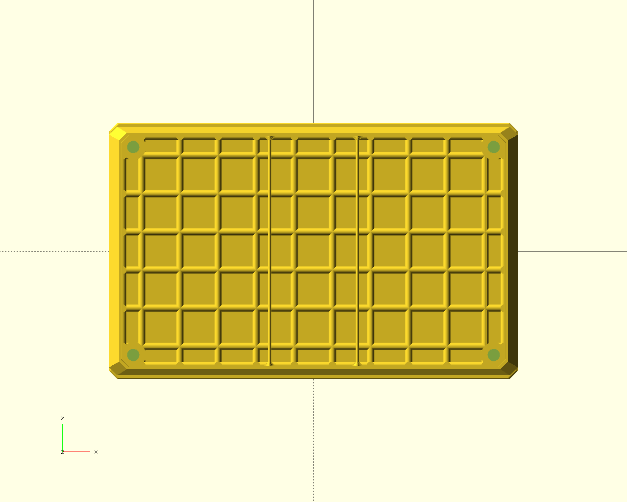
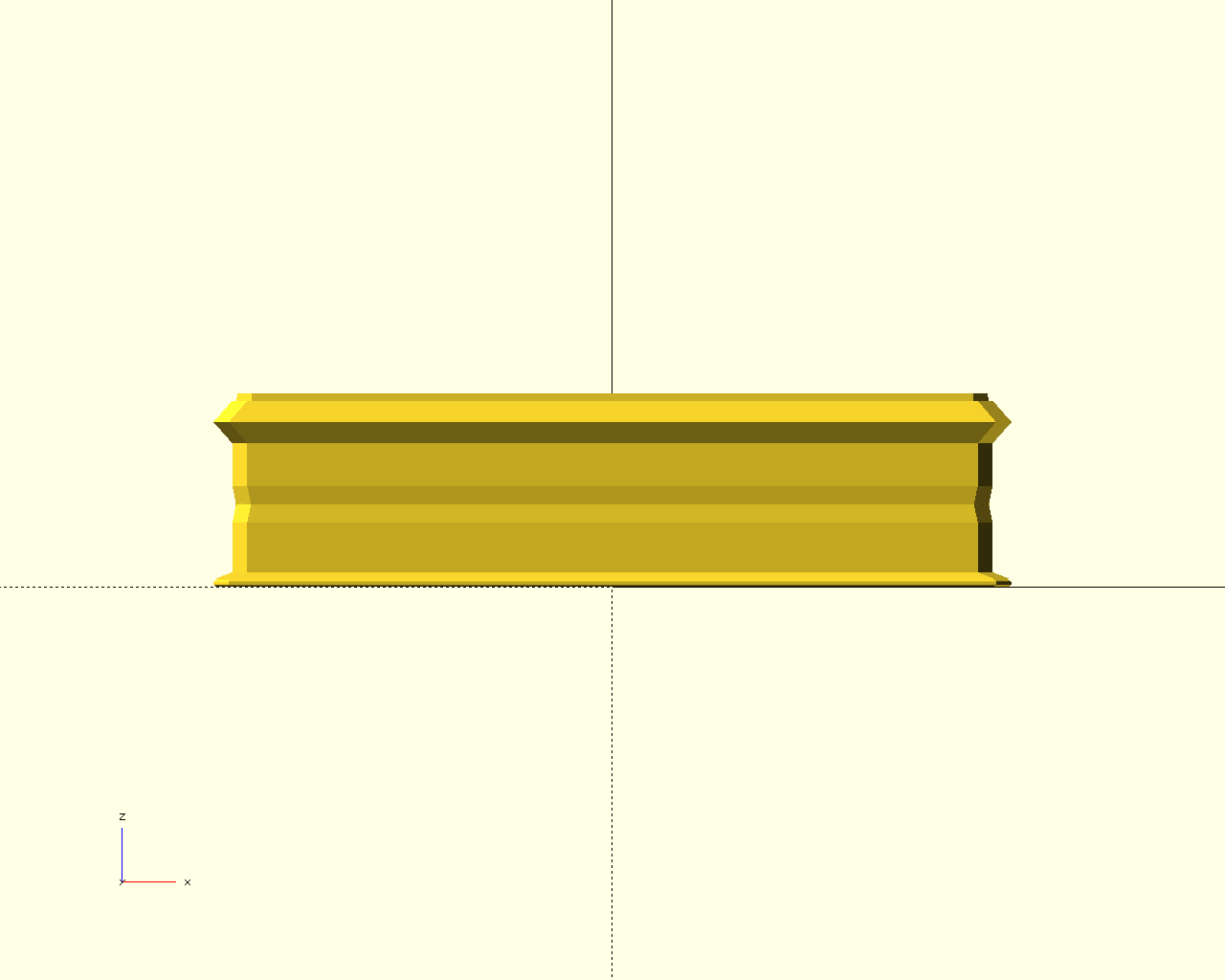
All height extrusions for walls, ribs, posts, etc, are performed by the function extrude_linear_mss(). This facilitates flexible scaling along the extrusion height as described in that functions documentation. The box bottom section example at the end of this page shows how this scaling can be used to create features, such as corner rounding and face protrusion, along the lid and box height.
The height of the exterior walls and the box lid are the result of extrusions produced using the function extrude_linear_mss(). The height can be specified as a single decimal value or may be specified as list of scaled sections along the height. For a description on specifying scaled extrusions see the documentation for this extrusion function.
By way of the parameter lip, the box walls can have an overhang that interfaces with adjacent wall or lid sections. The adjacent section should be constructed with an opposite lip orientation using the mode configuration.
| name | schema |
|---|---|
| lip | [ mode, height, width, taper, alignment ] |
| e | data type | default value | parameter description |
|---|---|---|---|
| 0 | integer | required | mode |
| 1 | decimal | wth | height |
| 2 | decimal | 45 | base width percentage of wall |
| 3 | decimal | 10 | top taper width percentage of wall |
| 4 | integer | 0 | alignment |
Integer value is binary encoded.
| b | description |
|---|---|
| 0 | upper and inside edge of wall |
| 1 | upper and outer edge of wall |
| 2 | lower and inside edge of wall |
| 3 | lower and outer edge of wall |
A lip pocket can be generated by using an appropriately sized inside and outer lip together. A corresponding lip pocket-insert can be approximated by using an inside lip with an alignment in the wall center (minimum lip gap).
| v | description |
|---|---|
| 0 | maximum lips gap |
| 1 | minimum lips gap with backfield |
| 2 | minimum lips gap |
Only inside edge lips may be aligned. Outer edge lips are always aligned with the outer edge of the box wall exterior.
The exterior box walls and lid rigidity can be reinforced using a this options to configure and construct a grid of rib-like structures which are embed on the interior surface of the walls and lid.
| name | schema |
|---|---|
| rib | [ mode, extrusions, coverage, counts ] |
| extrusions | [ base, x-extrusion, y-extrusion ] |
| e | data type | default value | parameter description |
|---|---|---|---|
| 0 | integer | required | mode |
| 1 | datastruct | (see below) | base and height extrusions |
| 2 | decimal-list-3:1 | decimal | 10 | [x, y, h] coverage percentage |
| 3 | integer-list-3:1 | integer | (calculated) | [x, y, h] count override |
Integer value is binary encoded.
| b | description |
|---|---|
| 0 | no ribs on the lid |
| 1 | no ribs on the x-positive wall |
| 2 | no ribs on the y-positive wall |
| 3 | no ribs on the x-negative wall |
| 4 | no ribs on the y-negative wall |
| 5-6 | lip coverage count (2-bit encoded integer) |
| 7 | offset all ribs to bottom of lower lip |
| e | data type | default value | parameter description |
|---|---|---|---|
| 0 | decimal | wth | rib base width |
| 1 | decimal-list-2 | [[wth, rib_edx]] | x-axis oriented rib height extrusion |
| 2 | decimal-list-2 | [[wth, rib_edy]] | y-axis oriented rib height extrusion |
The constants rib_edx and rib_edy are defaults that approximates a half-ellipse rib-like shape. To specify alternative custom extrusions, see the documentation for the extrusion function extrude_linear_mss().
The parameter wall may be used to define one or more interior walls to be constructed. There are two types which correspond to walls parallel to the x-axis (type 0) or y-axis (type 1). Each wall instance may be moved, scaled, or rotated.
| name | schema |
|---|---|
| wall | [ configuration, instances ] |
| configuration | [ mode, defaults ] |
| defaults | [ w, h, vr, vrm ] |
| instances | [ instance, instance, ..., instance ] |
| instance | [ type, move, scale, rotate, size, h, vr, vrm ] |
| e | data type | default value | parameter description |
|---|---|---|---|
| 0 | datastruct | required | configuration |
| 1 | datastruct | required | instances |
| e | data type | default value | parameter description |
|---|---|---|---|
| 0 | integer | required | mode |
| 1 | datastruct | (see below) | defaults |
Integer value is binary encoded.
| b | description |
|---|---|
| 0-1 | wall end rounding {0:none, 1:bevel, 2:fillet, 3:round-out} |
| 2-4 | wall top rounding (1) |
| 5-7 | wall base rounding (1) |
| 8-9 | wall on lips {0:none, 1:one, 2:both} |
| 10 | offset all walls to bottom of lower lip |
(1) The bits 2-4 and bits 5-7, configure the rounding mode for the wall top and wall base, respectively. The 3-bits integer values are indexed to the rounding options as summarized in the following table:
Integer value is binary encoded.
| v | wall top rounding | wall base rounding |
|---|---|---|
| 0 | none | none |
| 1 | bevel-in | bevel-in |
| 2 | round-in | round-in |
| 3 | fillet-in | fillet-in |
| 4 | bevel-out | bevel-out |
| 5 | fillet-out | fillet-out |
| 6 | round-out | round-out |
| e | data type | default value | parameter description |
|---|---|---|---|
| 0 | decimal | wth | width |
| 1 | datastruct | cfg_he | extrusion |
| 2 | decimal-list-4 | decimal | wth | rounding radius |
| 3 | integer-list-4 | integer | cfg_vrm | rounding mode |
The constants cfg_he and cfg_vrm define defaults that may be used to round the top, base, and edges of a wall.
| e | data type | default value | parameter description |
|---|---|---|---|
| 0 | integer | required | type {0: x-axis, 1:y-axis} |
| 1 | decimal-list-3:2 | decimal | [0, 0, 0] | move |
| 2 | decimal-list-3:2 | decimal | [1, 1, 1] | scale |
| 3 | decimal-list-3:1 | decimal | [0, 0, 0] | rotate |
| 4 | decimal-list-2 | tdef_s | size |
| 5 | decimal-list-2 | tdef_he | extrusion |
| 6 | decimal-list-4 | decimal | tdef_vr | rounding radius |
| 7 | integer-list-4 | integer | tdef_vrm | rounding mode |
The constants tdef_s, tdef_he, tdef_vr, and tdef_vrm are default values that depend on the wall type being constructed. For example, tdef_s = [max_x, wth] for wall type 0 and tdef_s = [wth, max_y] for wall type 1. These default may be overridden to provide custom wall sizes, wall rounding and/or height extrusions for each wall instance.
This parameter may be used to define one or more screw posts for securing covers, circuit boards, mounts, and the like. There are two types of predefined posts; normal posts and recessed access posts. Recessed posts have a widened access tunnel where screws can be inserted through and below the surface where the post is attached. All posts (and holes) may be rounded at the bottom, to widen the contact with the the adjacent surface, or at the top, to enhance contact or smooth its edges. Each post instance consists of two holes, a post with optional fins, and can be aligned, moved, and rotated. The optional post fins can be either triangular or rectangular in shape.
| name | schema |
|---|---|
| post | [ configuration, instances ] |
| configuration | [ mode, defaults ] |
| defaults | [ hole0, hole1, post1, hole2, post2, fins0, fins1, calculation ] |
| hole, post (1) | [ d, h, ho, da, ha, vr, vrm ] |
| fins (2) | [ c, sweep-angle, w, d-scale, h-scale, vr, vrm ] |
| calculation | [ hole1-mul, hole1-add, post1-mul, post1-add, hole2-mul, hole2-add, post2-mul, post2-add ] |
| instances | [ instance, instance, ..., instance ] |
| instance | [ type, align. move, rotate, hole0, hole1, post, fins ] |
(1) All numbered and unnumbered holes and posts utilize this form. (2) All fins defaults and instances are of this form.
| e | data type | default value | parameter description |
|---|---|---|---|
| 0 | datastruct | required | configuration |
| 1 | datastruct | required | instances |
| e | data type | default value | parameter description |
|---|---|---|---|
| 0 | integer | required | mode |
| 1 | datastruct | (see below) | defaults |
Integer value is binary encoded.
| b | description |
|---|---|
| 0-1 | post rounding {0:none, 1:bevel, 2:filet} |
| 2-3 | fin rounding {0:none, 1:bevel, 2:filet} |
| 4 | post base rounded same as top {0:opposite, 1:same} |
| 5 | set auxiliary screw hole on opposite side of lid |
| 6 | re-calculate defaults with each instance (1) |
| 7 | post type that extends into lip height {0:normal, 1:recessed} |
| 8 | lip height extension count {0:one, 1:both} |
| 9 | offset all posts to bottom of lower lip |
(1) The post and secondary hole diameter defaults are calculated as shown under calculation described below. This mode bit controls when the calculation is performed; either when defaults are configured (b=0), or when a post instance is created (b=1).
| e | data type | default value | parameter description |
|---|---|---|---|
| 0 | datastruct | (see below) | hole0; the screw hole |
| 1 | datastruct | (see below) | hole1; post 1 aux hole |
| 2 | datastruct | (see below) | post1; normal-post |
| 3 | datastruct | (see below) | hole2; post 2 access hole |
| 4 | datastruct | (see below) | post2; recessed-post |
| 5 | datastruct | (see below) | fins0: triangular-fins |
| 6 | datastruct | (see below) | fins1: rectangular-fins |
| 7 | datastruct | (see below) | calculation |
| e | data type | default value | parameter description |
|---|---|---|---|
| 0 | decimal | 3.25 | diameter |
| 1 | decimal | (maximum) | height |
| 2 | decimal | 0 | height offset |
| 3 | decimal | 0 | diameter adjust (1) |
| 4 | decimal | 0 | height adjust (1) |
| 5 | decimal-list-4 | decimal | 0 | rounding radius |
| 6 | integer-list-4 | integer | 0 | rounding mode |
(1) The elements 3 and 4 are used for late adjustments to diameters and heights for posts and holes. By late, it is meant that they allow for dimension changes without affecting dependent value calculations. This is useful to construct screw holes gaps or for a diameter increase required for brass metal screw inserts, for example. Another example is for use in post height adjustment that allow clearance for circuit board mounting.
The default values for hole1, hole2, post1, and post2 are computed according to that outlined in the defaults calculation section below. The height and offsets are set based on the post height and other configured requirements.
| e | data type | default value | parameter description |
|---|---|---|---|
| 0 | integer | 4 | count |
| 1 | decimal | 360 | distribution angle |
| 2 | decimal | wth | width |
| 3 | decimal | 1/5 | post diameter fraction |
| 4 | decimal | 5/8 | post height fraction |
| 5 | decimal-list-3 | decimal | def_f0_vr | rounding radius |
| 6 | integer-list-3 | integer | def_f0_vrm | rounding mode |
The constants def_f0_vr and def_f0_vrm define defaults for fin rounding and may be overridden if needed. See the source code for more details.
| e | data type | default value | parameter description |
|---|---|---|---|
| 0 | integer | 4 | count |
| 1 | decimal | 360 | distribution angle |
| 2 | decimal | wth | width |
| 3 | decimal | 1/2 | post diameter fraction |
| 4 | decimal | 1 | post height fraction |
| 5 | decimal-list-4 | decimal | def_f1_vr | rounding radius |
| 6 | integer-list-4 | integer | def_f1_vrm | rounding mode |
The constants def_f1_vr and def_f1_vrm define defaults for fin rounding and may be overridden if needed. See the source code for more details.
| e | data type | default value | parameter description |
|---|---|---|---|
| 0 | decimal | 0 | hole1 multiplier |
| 1 | decimal | 0 | hole1 addition |
| 2 | decimal | 3.0 | post1 multiplier |
| 3 | decimal | wth/2 | post1 addition |
| 4 | decimal | 2.0 | hole2 multiplier |
| 5 | decimal | wth/2 | hole2 addition |
| 6 | decimal | 4.0 | post2 multiplier |
| 7 | decimal | wth/2 | post2 addition |
For hole1, hole2, post1, and post2, the diameters are calculated based on the following model:
where hole0 is the screw-hole diameter and wth is the configured wall thickness parameter value. This allow for a simple way to generate posts and holes that are dependent on the screw hole diameter. The multiplier and fixed additions for each hole and post may be configured to replace the values shown in the above table.
| e | data type | default value | parameter description |
|---|---|---|---|
| 0 | integer | required | type |
| 1 | integer-list-3:1 | undef | align |
| 2 | decimal-list-3:2 | [0, 0, 0] | move |
| 3 | decimal-list-3:1 | decimal | [0, 0, 0] | rotate |
| 4 | datastruct | (see note) | hole0; screw hole |
| 5 | datastruct | (see note) | hole1; aux hole |
| 6 | datastruct | (see note) | post |
| 7 | datastruct | (see note) | fins |
Integer value is binary encoded.
| b | description |
|---|---|
| 0 | post type {0:normal, 1:recessed} |
| 1 | fin type {0:triangular, 1:rectangular} |
The x, y, and z axis of the box can be aligned independently using this parameter.
| e | data type | default value | parameter description |
|---|---|---|---|
| 0 | integer | 0 | x-axis alignment |
| 1 | integer | 0 | y-axis alignment |
| 2 | integer | 0 | z-axis alignment |
| v | description |
|---|---|
| 0 | center of enclosure |
| 1 | positive exterior edge of lid |
| 2 | positive exterior edge of wall |
| 3 | positive interior edge of wall |
| 4 | negative interior edge of wall |
| 5 | negative exterior edge of wall |
| 6 | negative exterior edge of lid |
| v | description |
|---|---|
| 0 | bottom edge of lid |
| 1 | bottom edge of wall |
| 2 | middle of enclosure |
| 3 | middle of wall |
| 4 | top edge of wall |
| 5 | top edge of lip |
Integer value is binary encoded.
| b | description |
|---|---|
| 0 | size is specified for enclosure interior |
| 1 | remove features outside of enclosure envelope |
| 2 | scale interior with exterior wall during extrusion |
| 3 | do not limit wall rounding modes to bevel and rounded (1) |
(1) When rounding mode limiting is disabled, the rounding mode value, vrm, is no longer mapped to bevel or rounded and any mode of the function polygon_round_eve_all_p() may be used to round the box exterior walls and lid.
Project box bottom section example script
| top | front | right | diag |
|---|---|---|---|
 |  | 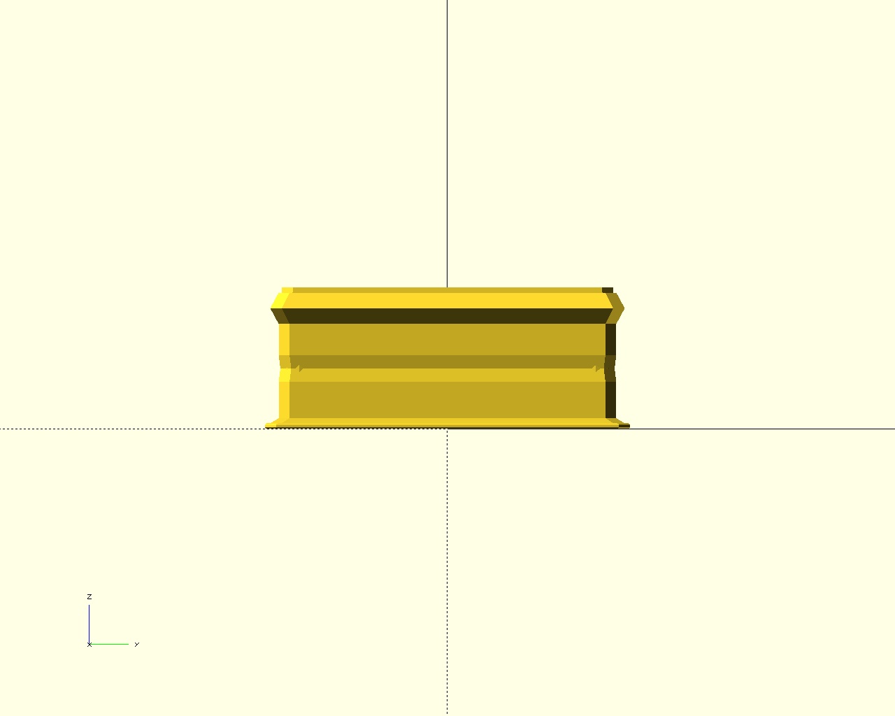 | 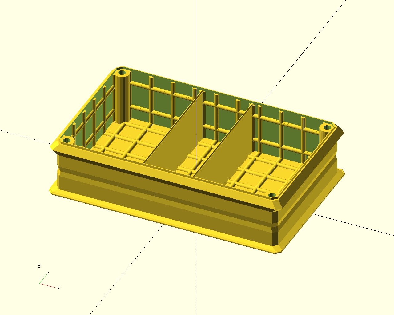 |
Definition at line 1019 of file project_box_rectangle.scad.
 Here is the call graph for this function: